Review the sections below for important information on product instilation and helpful hints. Before you jump into your transmission, get helpful insights and practical information designed to make your build a smooth one.
GEAR RATIO CALCULATIONS
FOR A COMPLETE LIST OF SUBARU AWD MODELS, DOWNLOAD THE PDF FROM RALLISPEC HERE OR GET STARTED WITH YOUR CALCULATIONS.
!!!CHECKING YOUR AXLE LENGTH IS REQUIERD FOR ALL INSTALLATIONS PRIOR TO OPERATION!!!
Axle length verification procedure:
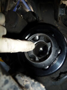
Step #1: Put chalk inside the CV conversion flange when first assembled.
Step #2: Place vehicle on hoist, fit the CV’s and axles on to chassis.
Step #3: Place vehicle suspension at full droop (trailing arm at its lowest point) – and turn the CV and axle assembly.
Step #4: Place vehicle suspension with the axle’s level and turn the axle and CV assembly.
Step #5: place vehicle suspension at full bump (trailing arm at highest point) – turn the CV and axle assembly.
Step #6: Take the inner CV out and see if any of the chalk has been taken off by the rotating assembly. Removal of chalk from the inner CV conversion flange during rotation of axle assembly is signs of contact and can cause premature failure of the transmission and/or transmission components. Adjustments must be made accordingly.
Signs of wear/damage to conversion flange will void the warranty!!!
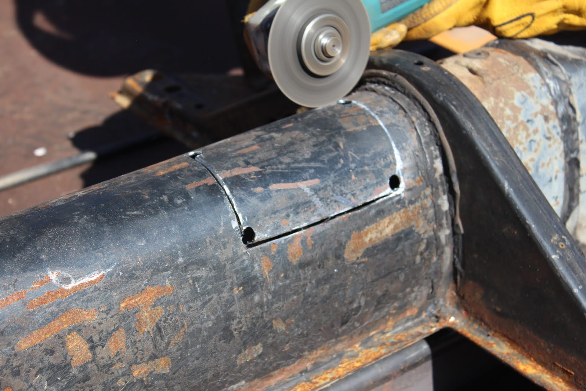
In Tunnel Access kit Instilation Instructions
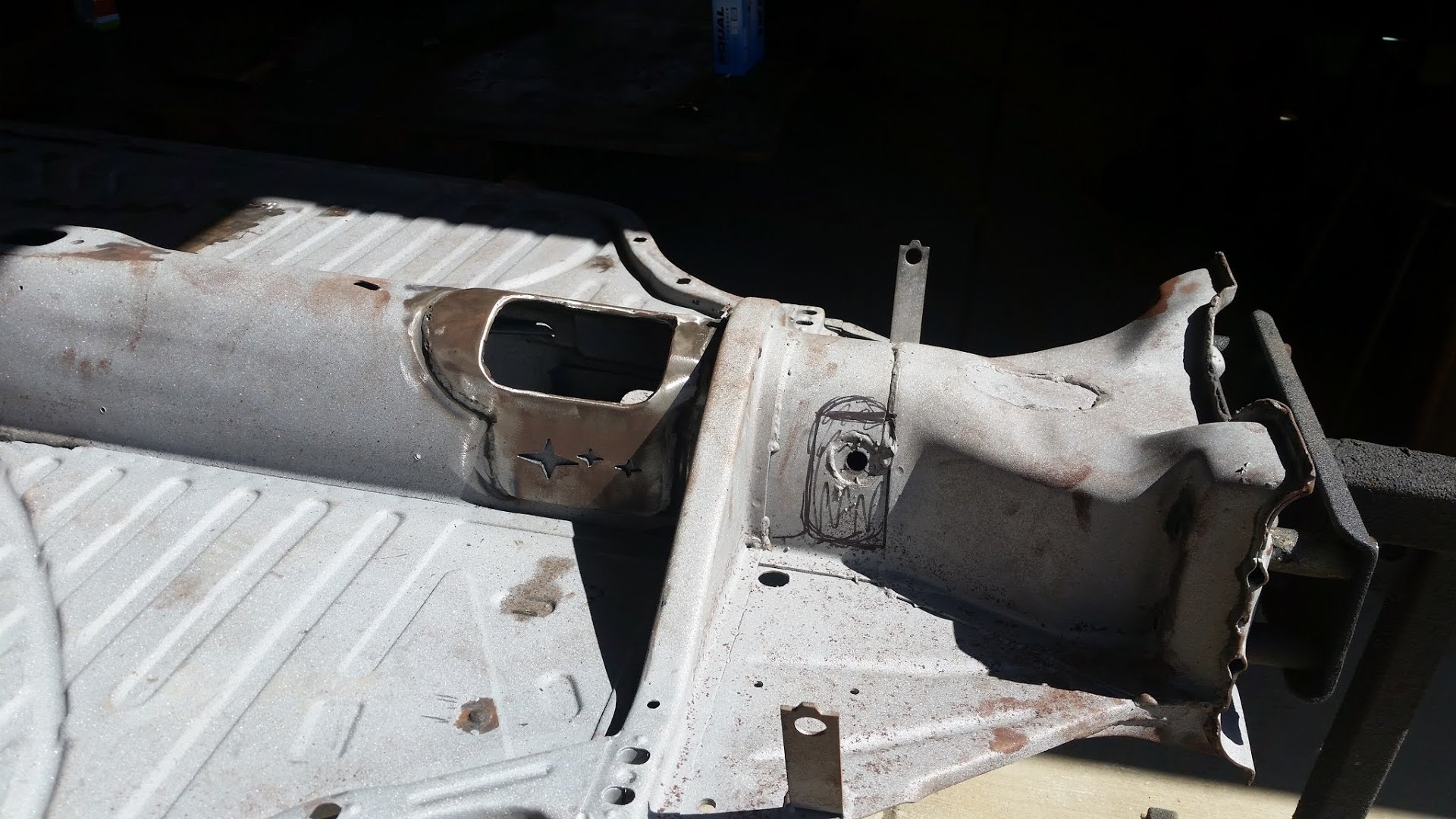
STEP 1 align-access-cover-mark-cutting-area
STEP 2 trace-the-corners-to-90-angle
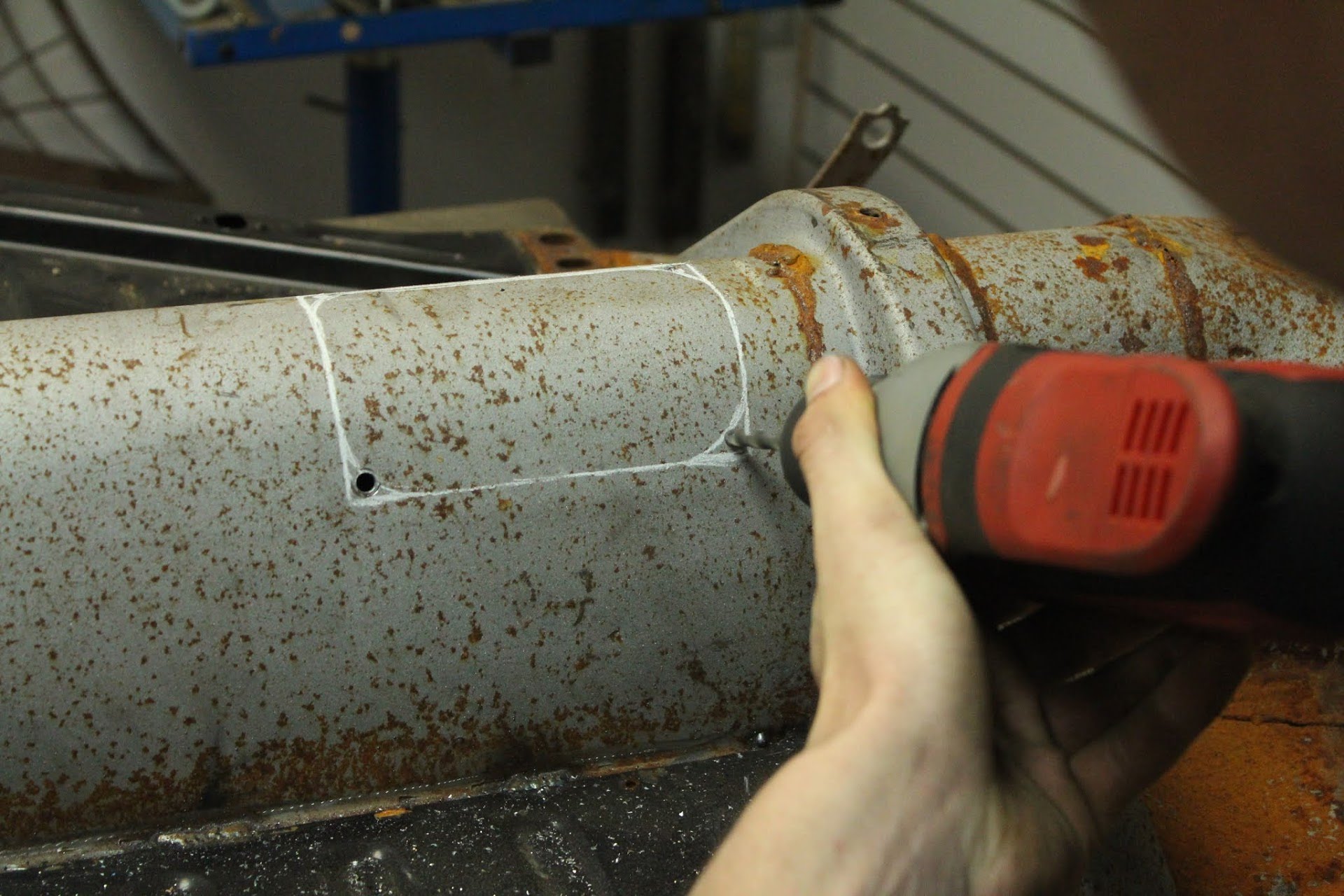
STEP 3 drill-holes-in-the-the-corners
STEP 4 remove-material-from-all-4-corners
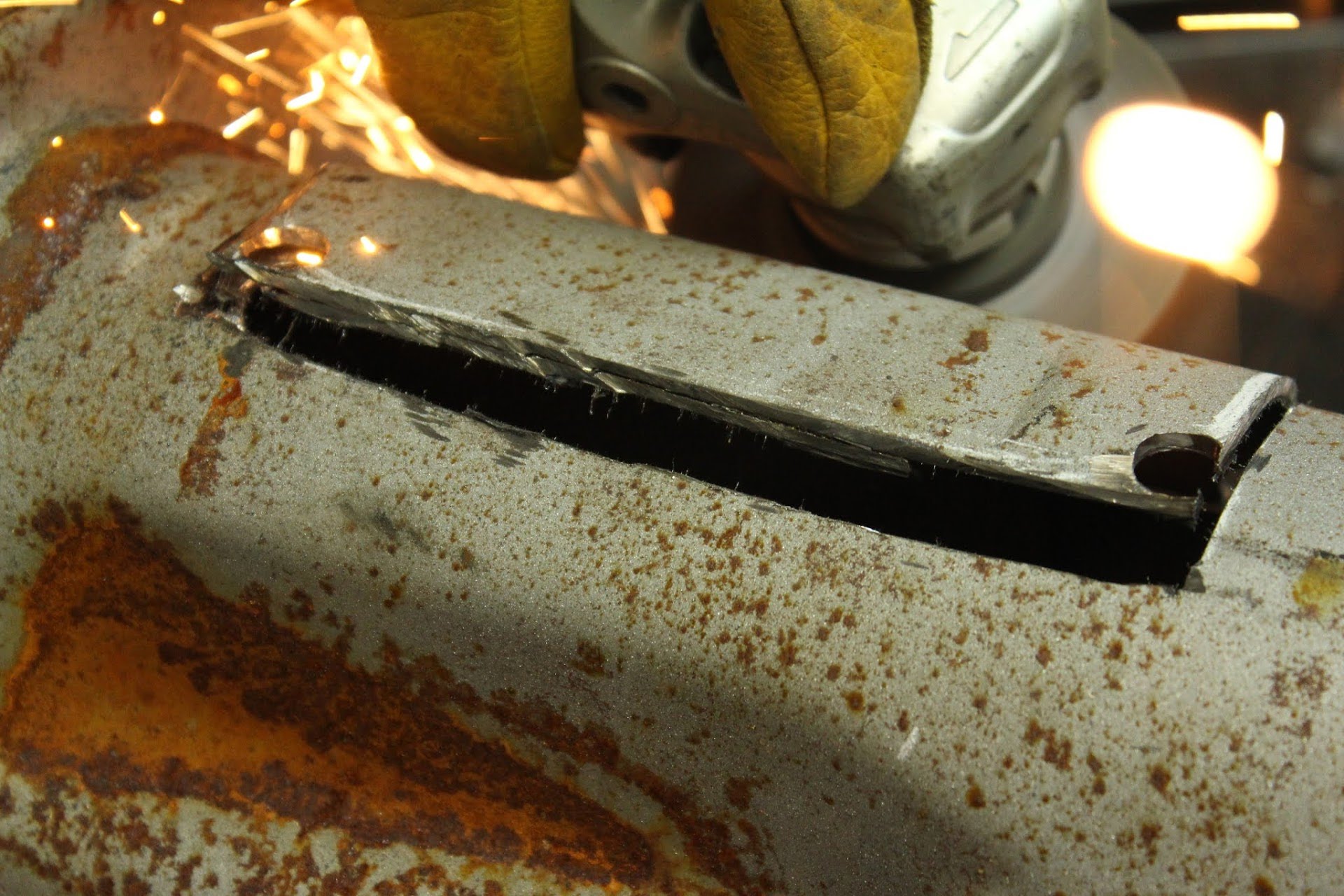
STEP 5 cut
cut-out-rectangle
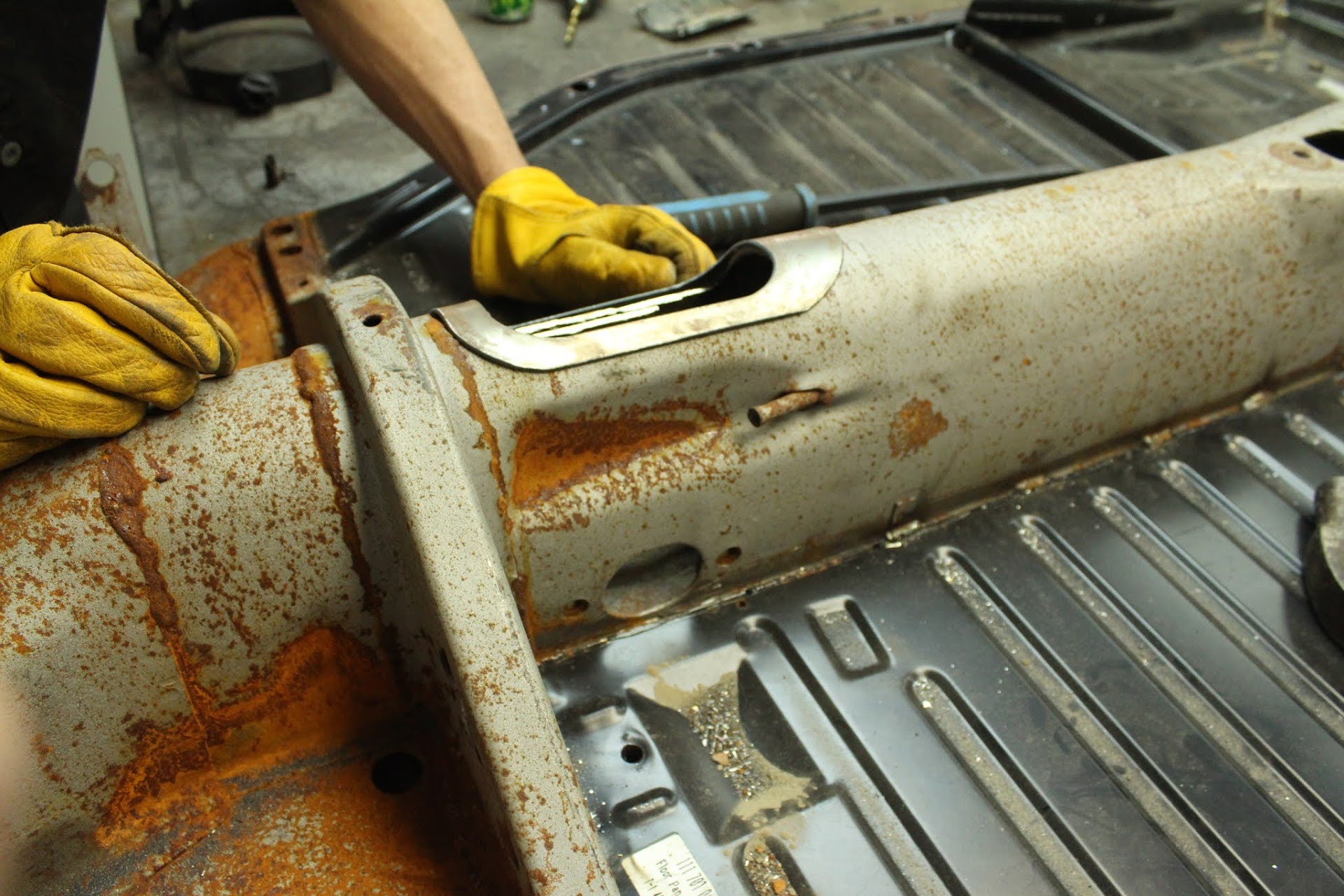
STEP 6 remove metal to access hole
STEP 6 check-access-plate-for-fitment
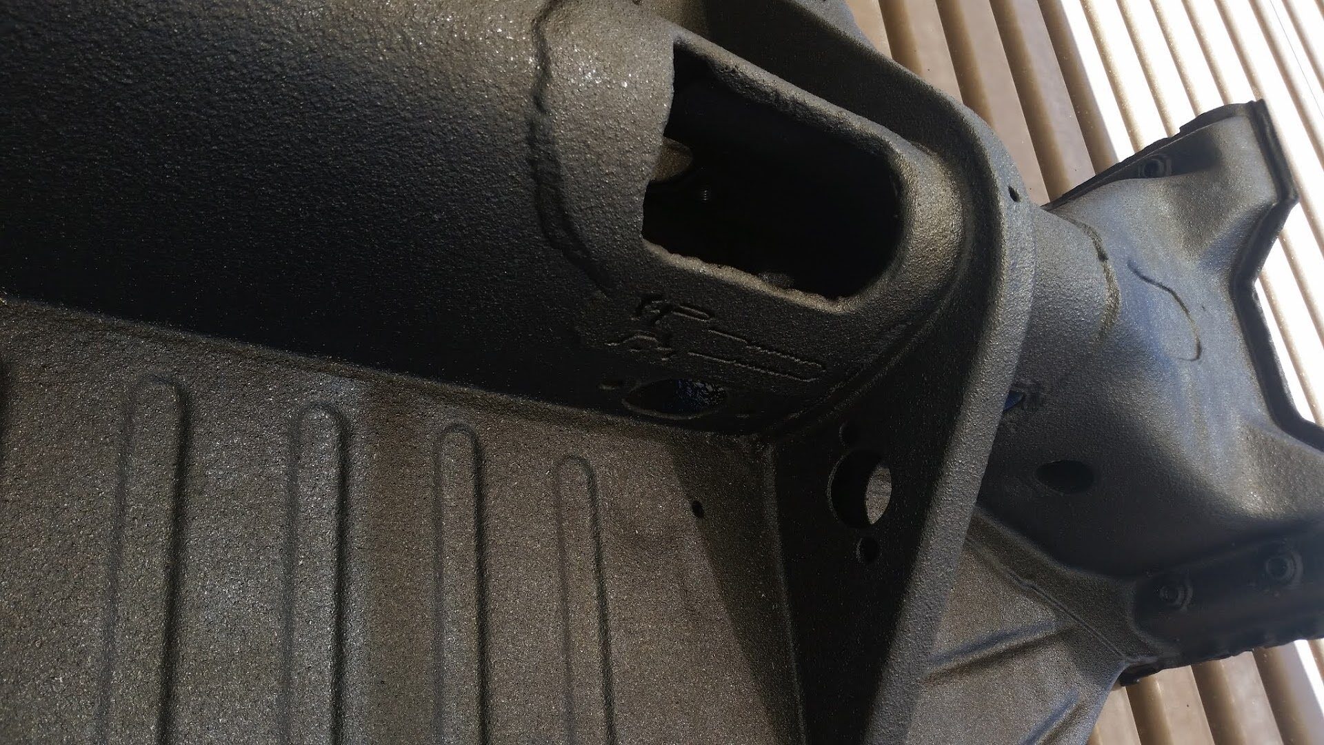
STEP 7 weld-access-cover-plate
STEP 8 finish with paint or coating
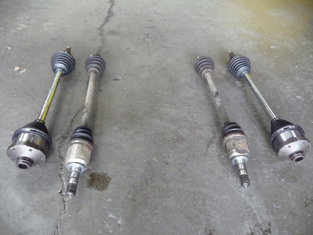
SUBIWORKS Monster CVs
How to measure, test, and assemble
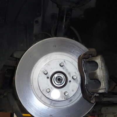
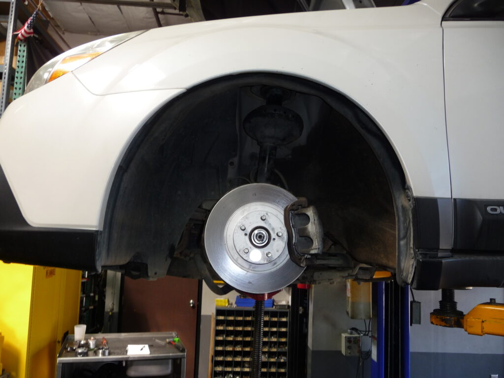
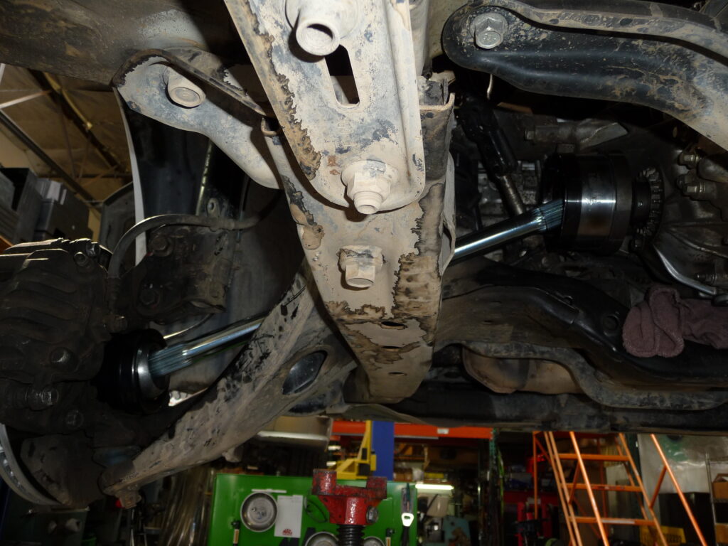
Place vehicle on 4 jack stands so all wheels can rotate freely.
Remove front wheels.
Remove front axle nuts.
Push axles in towards center of vehicle through hub.
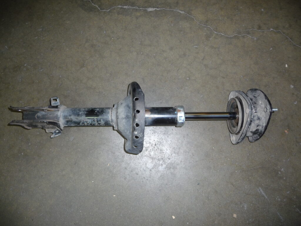
Remove both front struts complete while supporting hubs. We hang them with straps.
Remove the spring, bump stop, and covering from one of the struts. Be sure to use a spring compressor. The spring is under tension and can cause severe injury. This strut will be used to measure both sides of the vehicle. Re-install top hat and tighten nut.
7. Install this strut back on the original side it came off of.
8. Remove both sway bar end links in order to cycle each side separately.
9. Transmissions that have stub ends in them jump to step 13
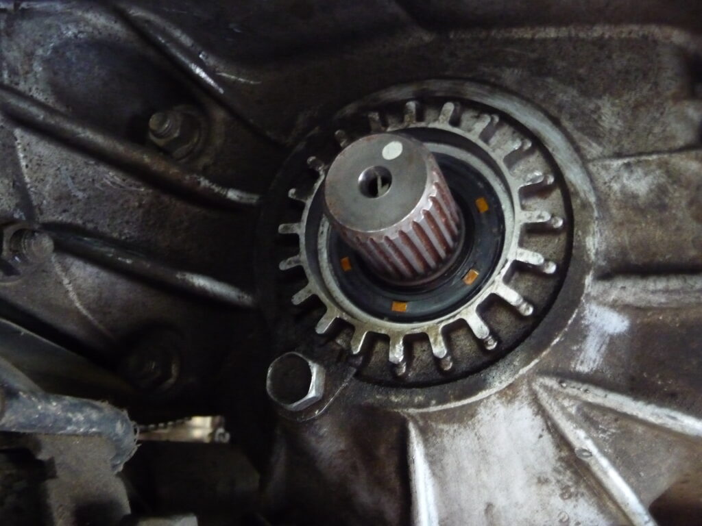
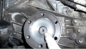
10. Remove axle seal from transmission and replace with new provided seals. These seals are side specific. There is an R and L can be found on the seal surface. Driver side is Left. Some models require removing the bearing adjuster. Make sure you mark the original position and only do 1 side at a time. These caps are very important to the ring and pinion and should be put back the exact way they came out. Make sure not to damage the o-ring or sealing surface. Apply oil to o-ring before reinstalling it. See shop manual if you are unsure on how to replace these seals.
11. Install snap ring on stub end and install into transmission with a soft rubber mallet.
12. Repeat seal install and stub end on other side.
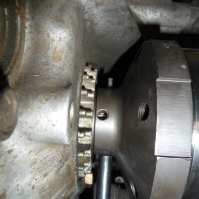
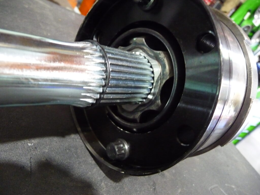
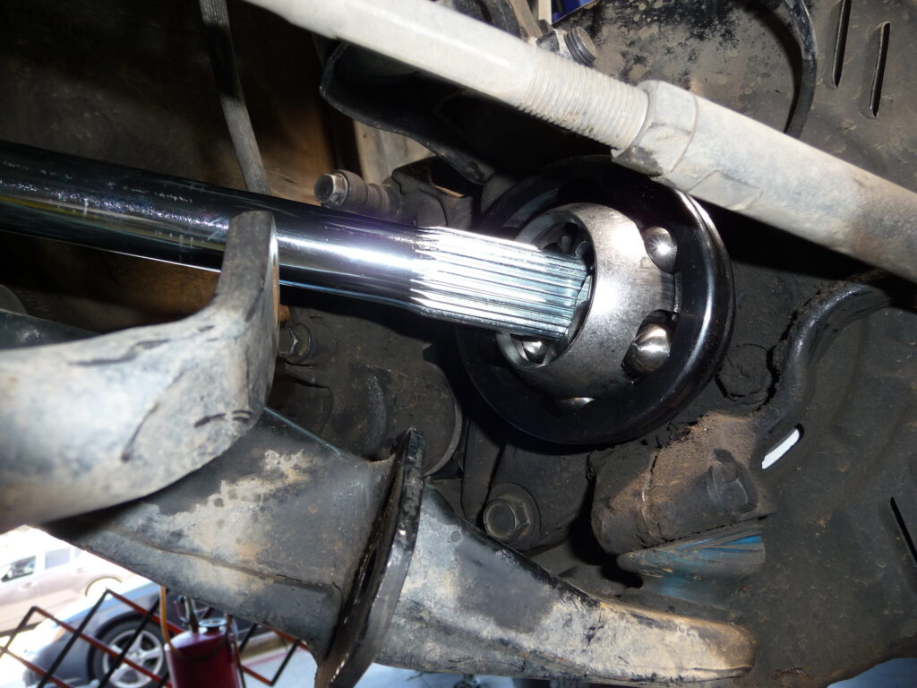
13. Install the inner flanges and roll pins to the stub ends. If the flange has 2 sets of holes use the inner most holes if possible. This allows for the longest possible axle. The holes are offset. Before the roll pin is installed make sure the punch will go all the way through the hole. If not, take off flange and rotate 180* and try putting the punch through. Once the punch will go through then the roll pin can be installed. 14. Install the outer CV (and spacer if required, bolt in wheel bearings require this, spacer is on the outside before the axle nut) and tighten nut to factory specifications.
15. With the suspension at full droop (suspension dropped all the way down) measure the distance from the groove in the outer CV to the inner shaft inside the flange on the side where the strut was reinstalled.
16. Record the distance between these 2 points
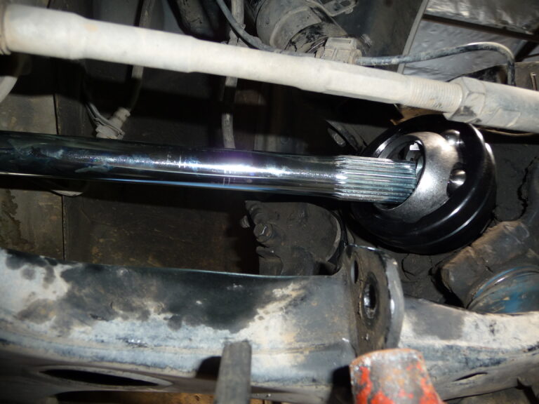
17. Jack up the hub until the strut bottoms out at full bump. Measure distance again and record the measurement.
18. Take the shortest measurement between the 2 and add 1/2” to the measurement. This is the length for the axle shaft needed.
19. Remove strut and install on opposite side. Repeat steps 15-18. Measurements may be different.
20. New axles may be marked R and L on the ends. Be sure to use correct sides.
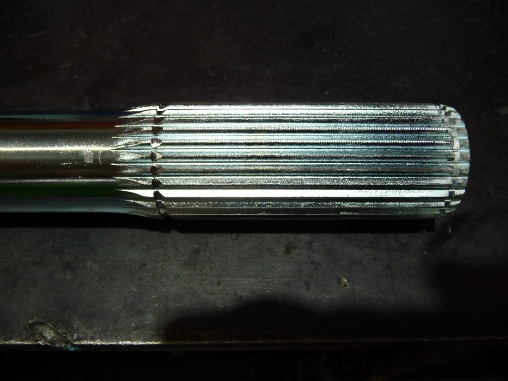
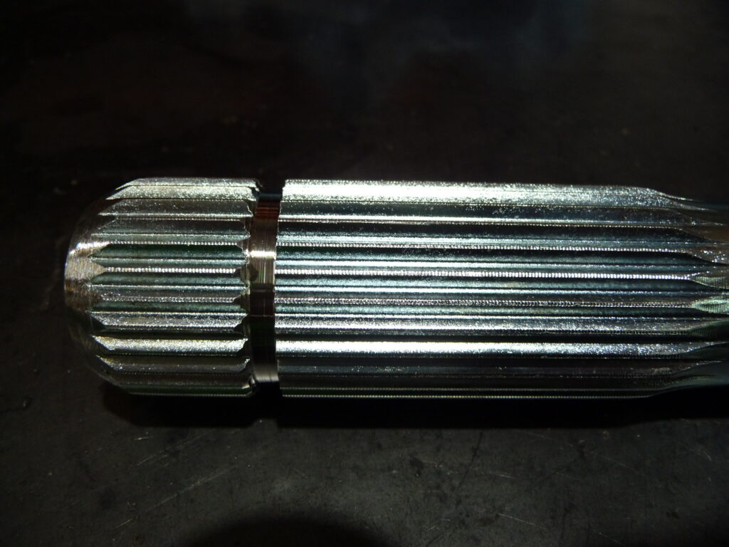
21. On the inner spline there needs to be a second snap ring groove made at the end of the splines before it tapers off. This groove should be approximately the same width of the existing groove at the end of the shaft.
22. If the shaft needs to be cut to proper length, cut off the other end to proper length and taper the splines to aid in install.
23. 1” from tapered end there needs to be another groove cut into the splines, .100” wide. Verify groove is wide enough for the snap ring.
24. Assemble axle dry (without grease) and install on side with bare strut installed. Tighten outer axle nut and install 2 bolts to mount inner CV assembly to flange.
25. At full droop verify axle does not bind (there should be little play on the shaft) and turn from lock to lock while rechecking for axle shaft binding.
26. Jack up hub to full bump and turn lock to lock while verifying axle shaft never binds or gets tight.
27. Repeat steps 25 and 26 on opposite side. Move strut to other side and install dry assembled axle for correct side.
If any binding occurs on either side then the axle length must be shortened until binding stops. Only take off ¼” at a time from the non-tapered side. Each time a new groove must be added to reinstall the snap ring. Reinstall and re-test until there is no more binding.
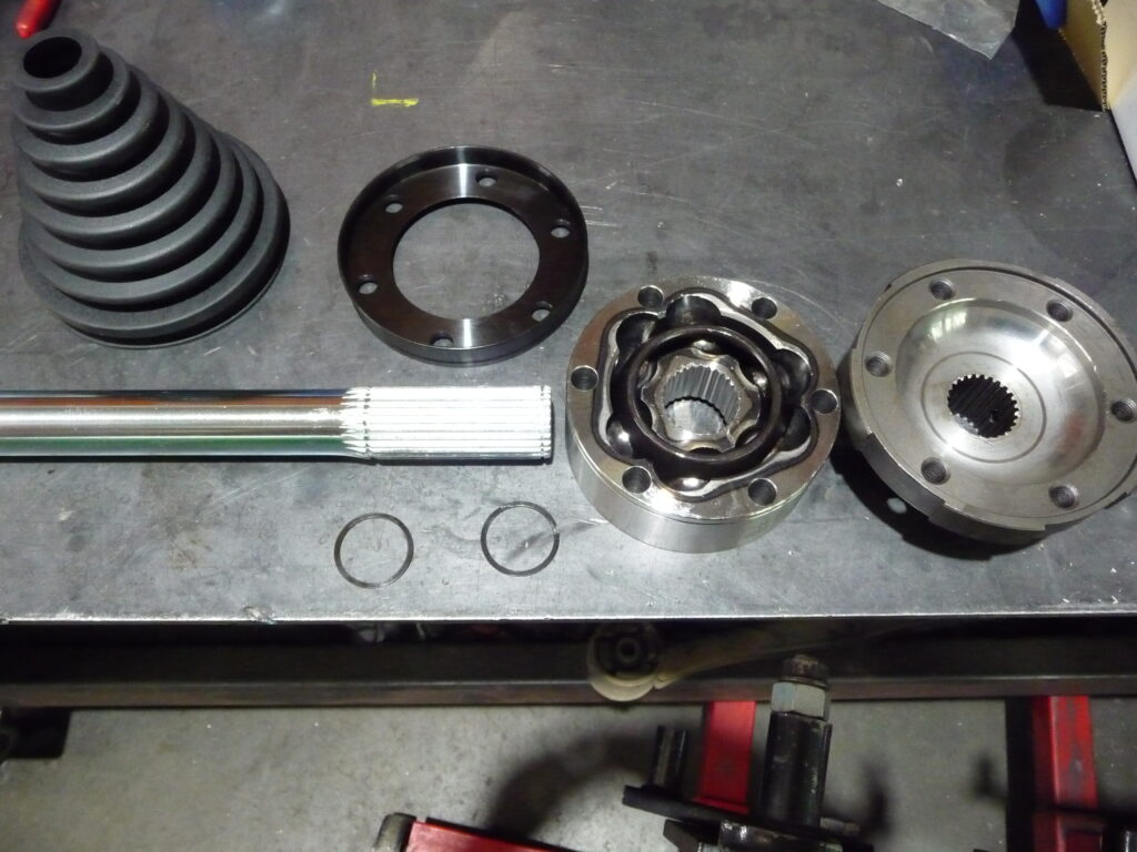
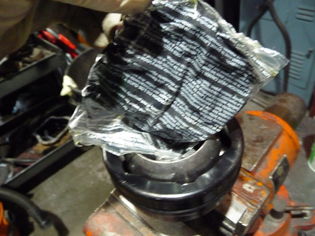
28. Remove both axles and reassemble with grease, boots, and clamps.
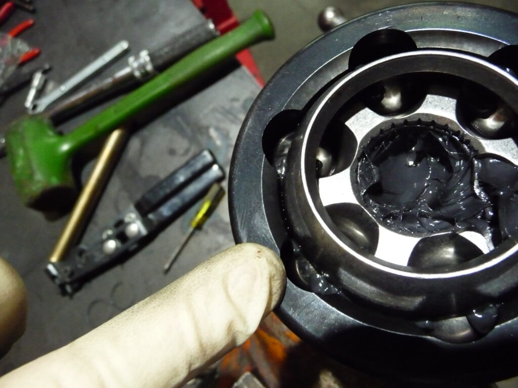
29. Remove outer CV joint and fill with grease until it pushes past the balls.
30. Install shaft until it clips in the snap ring. This should push more grease past the balls. Rotate shaft in a circular motion mixing grease into balls and cage. Once grease is mixed in adequately, add some more grease to the top of the cage and balls around the shaft.
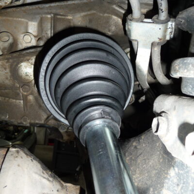
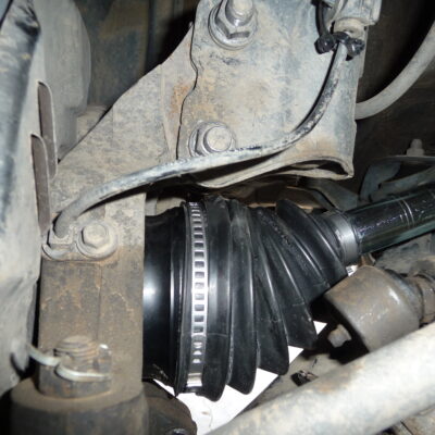
31. Slide outer boot down shaft. Remove any grease in boot mounting surface and install boot. Install both clamps. Make sure not to over tighten clamps, this will cause premature failure of the boot. When the clamp is tight the boot will no longer spin on the joint or shaft.
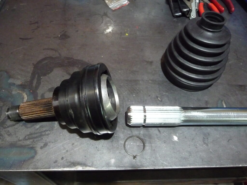
32. Slide inner clamp and inner boot down the shaft to leave room for assembly.
33. Install one snap ring on inner most groove.
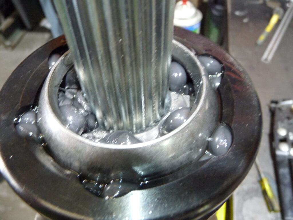
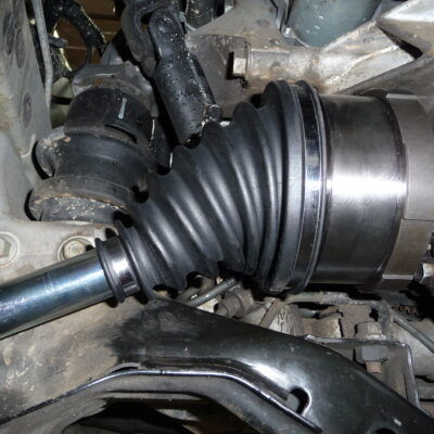
34. Grease inner CV assembly so all mating surfaced are coated. Install boot ring and CV assembly with the small cage opening of the CV towards end of shaft.
35. At this point the axle can be bolted into place… or you can remove the inner flange from the vehicle and completely build the axle off the vehicle. This seems to be the easier way. Make sure the cv bolts get torque to 50lbs. You can re-torque after 500 miles. New bolts will stretch a bit at first.
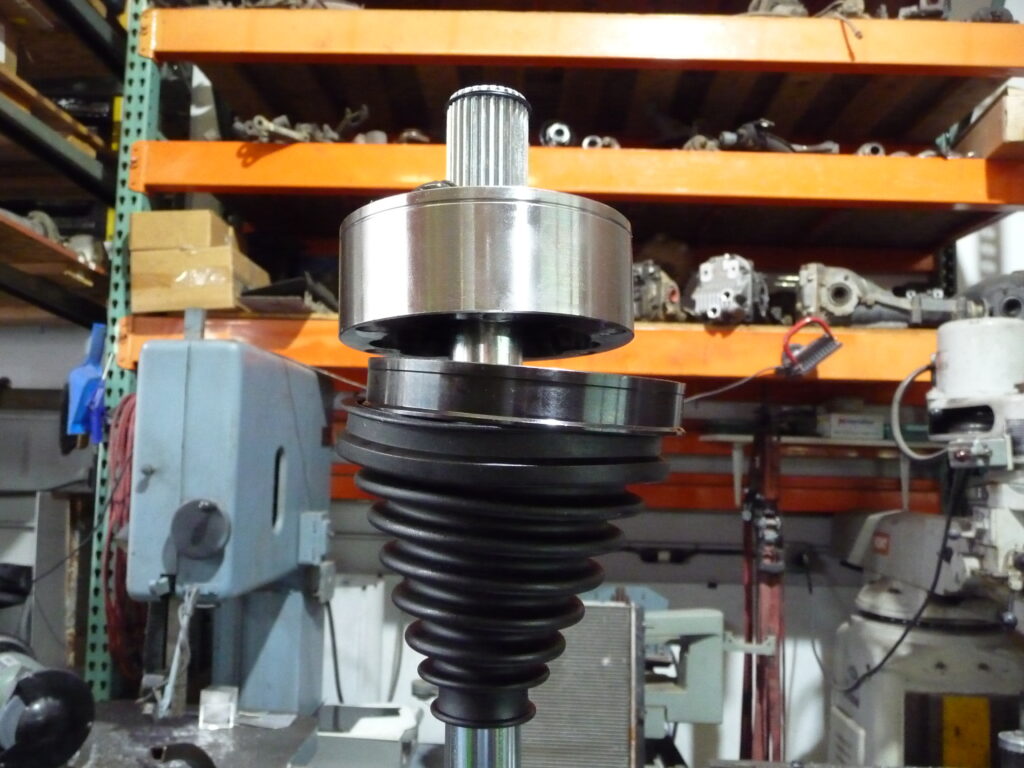
36. Once shafts are built the vehicle can be reassembled and with loaded struts. Don’t forget to reattach the sway bar (if you plan on keeping it).
37. Install the axles and make sure the boots and clamps clear by 1/4” all the way around. Torque the axle nut to factory specifications. ( re-torque after 100 miles)
38. Road test and enjoy!
These CVs are meant to last which means you will have to remove, inspect and re-grease them occasionally. We recommend doing this every year if you abuse your vehicle like we do!!
Please remember this is an off road part, different than factory specifications.
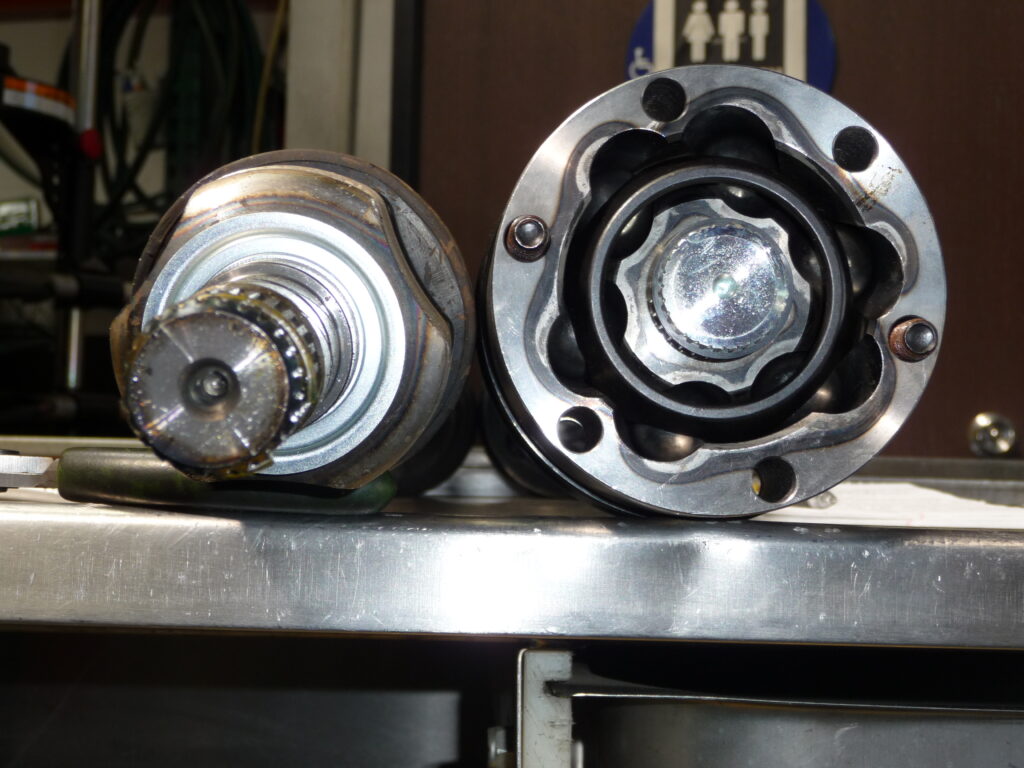
The balls, cage, and star can be replaced if any scaring is found during service. We recommend buying a spare inner and a spare outer set of internals along with 1 inner and 1 outer boot with clamps.
We carry spares in our vehicle for long trips so they can be rebuilt on the road without delay should it be necessary.
If you have any questions please call Subiworks at (951)691-5679.